Protocols
Common Port Numbers Quick Reference
Section titled “Common Port Numbers Quick Reference”| Protocol | Port(s) | Transport |
|---|---|---|
| HTTP | 80 | TCP |
| HTTPS | 443 | TCP |
| DNS | 53 | UDP/TCP |
| DHCP | 67 (server), 68 (client) | UDP |
| SSH | 22 | TCP |
| Telnet | 23 | TCP |
| FTP | 20 (data), 21 (control) | TCP |
| TFTP | 69 | UDP |
| SNMP | 161 (agent), 162 (trap) | UDP |
DHCPv4 Dynamic Host Configuration Protocol
Section titled “DHCPv4 Dynamic Host Configuration Protocol”| Packet | Device | Notes |
|---|---|---|
| DHCP Discover | Host | - Host sends out a broadcast packet seeking a DHCP Server on Network - Packet source IP 0.0.0.0 - Packet Destination IP 255.255.255.255 |
| DHCP Offer | Server | - Server Responds with a DHCP Offer Packet which contains a IP Address, Subnet Mask, lease time and Default Gateway |
| DHCP Request | Host | - Host responds to the server accepting the DHCP Offer - This stage is called a request as the host is formally requesting the offered IP. - Should there be multiple DHCP offers the other offers are notified they were not successful and the ip’s not being used are return to respective pools. |
| DHCP Acknowledge | Server | - Server Acknowledges the host has accepted the offer and registers the IP address has been assigned to the host. |
Ports: DHCP uses UDP Port 68 for client and port 67 for server
Extended Interior Gateway Routing Protocol - EIGRP
Section titled “Extended Interior Gateway Routing Protocol - EIGRP”EIGRP is an advanced distance vector protocol type, Cisco Proprietary and is a DUAL (Diffusing Update Algorithm) algorithm
def eigrp(min_bandwidth, load, total_delay, relability, k1, k2, k3, k4, k5):  m1 = 0 if k1 == False else 1 * ((10**7) / min_bandwidth)  m2 = 0 if k2 == False else (((10**7) / (1*min_bandwidth))/(256-load))  m3 = 0 if k3 == False else (1 * total_delay)/10  m4= 0 if k4 == False else 1  m5 = 0 if k5 == False else (1+ relability)  answer = 256*((m1+m2+m3)*(0 if m5 == False else m4))  print(answer)  return answer

eigrp(1200,900000000,10,5,True,True,True,True,True)
Open Shortest Path First - OSPFv2
Section titled “Open Shortest Path First - OSPFv2”Link state based protocol - industry standard.
- Version 2 uses IPv4 and Version 3 uses IPv6
- Establishes Neighbour Adjacencies
- Exchanges Link-State Advertisements
- Builds a Topology Table
- uses SPF algorithm
There are single area and multiple area
- Neighbour Table
- Topology Table
- Routing Table
Message Structure
Section titled “Message Structure”Link State Packet Types
- Type 1: Hello
- Type 2: Database Description DBD
- Type 3: Link-State Request (LSR)
- Type 4: Link-State Update (LSU)
- Type 5: Link-State Acknowledgment (LSA)
Spanning Tree Protocol
Section titled “Spanning Tree Protocol”Automated topology building protocol which avoids “loops” in the networks logical topology. At a basic level it ensures there are no bridge loops or broadcast radiation (broadcast storms). In addition the protocol also ensures redundant links where possible for fail-over events creating fault tolerant paths.
Switches flood broadcast packets and in a redundant topology without STP it can cause broadcast loops.
BPDU Frames are special frames used in the STP protocol to determine a ports role in the topology a BPDU Frame includes a Bridge ID which consists of [Priority Number + VLAN ID + MAC ADDRESS]
STP Order of operations
- Determine root bridge by electing a switch with lowest value bridge ID (The network admin will ensure to use priority correctly in the topology to not leave this to luck.)
- Ports on a root bridge are labelled designated ports and lead
awayfrom the root bridge. - Root ports are ports on the non root switches which forward data to the root bridges.
- Root ports are selected by lowest path cost (fastest link to root bridge),
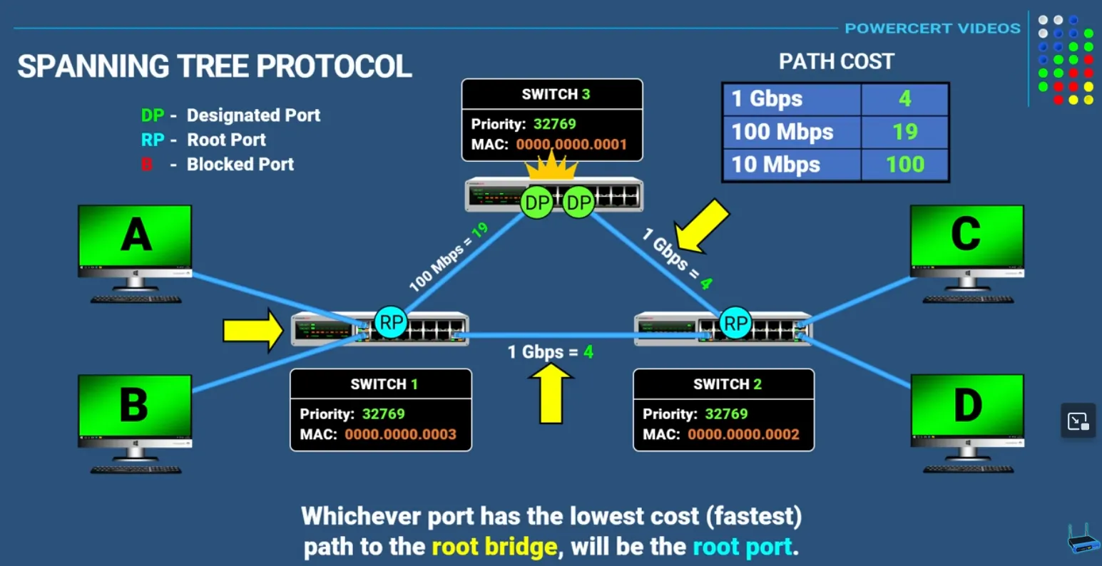
Root Port Calculation Table
| Link Speed | Cost |
|---|---|
| 1 Gbps | 4 |
| 100 Mbps | 19 |
| 10 Mbps | 100 |
In any segment, the port that is not elected as a Root Port or a Designated Port enters the Blocking State.
STP Port States
| State | Purpose | Forwarding Data? |
|---|---|---|
| Blocking | Prevents loops; receives BPDUs only. | No |
| Listening | Building the topology; cleaning out old entries. | No |
| Learning | Populating the MAC address table. | No |
| Forwarding | Normal operation. | Yes |
| Disabled | Port is administratively down. | No |
PortFast
Section titled “PortFast”This is a configuration used on “edge” ports (connecting to PCs or Servers). It allows the port to skip the Listening/Learning phases and go straight to Forwarding.
Warning: Never enable PortFast on a port connected to another switch, as it bypasses the loop-prevention mechanism!
Application Layer Protocols
Section titled “Application Layer Protocols”DNS Domain Name Service
Section titled “DNS Domain Name Service”DNS translates human-readable domain names to IP addresses.
Key Characteristics:
- Port 53: Uses both UDP (queries) and TCP (zone transfers)
- Hierarchical structure: Root → TLD → Authoritative nameservers
- Record types: A (IPv4), AAAA (IPv6), CNAME (alias), MX (mail), NS (nameserver), PTR (reverse)
- Caching: Reduces lookup time and server load
- Recursive vs Iterative queries
HTTP (Hypertext Transfer Protocol)
Section titled “HTTP (Hypertext Transfer Protocol)”HTTP is the foundation of data communication on the World Wide Web. It’s a request-response protocol where clients (typically web browsers) send requests to servers, which then respond with the requested resources.
Key characteristics:
- Stateless: Each request is independent; the server doesn’t retain information between requests
- Port 80: Default port for HTTP communication
- Request methods: GET (retrieve data), POST (submit data), PUT (update), DELETE (remove), HEAD, PATCH, etc.
- Status codes:
- 2xx (success) - e.g., 200 OK
- 3xx (redirection) - e.g., 301 Moved Permanently
- 4xx (client errors) - e.g., 404 Not Found
- 5xx (server errors) - e.g., 500 Internal Server Error
HTTPS (HTTP Secure)
Section titled “HTTPS (HTTP Secure)”- HTTP over TLS/SSL encryption
- Port 443
- Encrypts data in transit, preventing eavesdropping and tampering
- Now the standard for virtually all websites
HTTP versions:
- HTTP/1.1: Persistent connections, chunked transfer encoding
- HTTP/2: Multiplexing, header compression, server push
- HTTP/3: Built on QUIC protocol (UDP-based) for improved performance
Transport Layer Protocols
Section titled “Transport Layer Protocols”Choice of protocol is important when determining criticality of packets being sent across the network.
UDP - User Datagram Protocol
Section titled “UDP - User Datagram Protocol”Protocol used in streaming or real time communications - no acknowledgement of receipt of packets - protocol defined as connection-less:
- UDP is not shackled by overhead
- It allows for packet loss and is used where overall packet loss being OK (streaming a video)
TCP - Transmission Control Protocol
Section titled “TCP - Transmission Control Protocol”Protocol used where packet loss is a major concern (financial apps, transaction data) - acknowledgement of receipt of packets - protocol defined as connection oriented:
- Reliability built in with a mechanism that ensures fewest number of packets get dropped
- If any packets are dropped they will be automatically re-transmitted.
- Each segment has a sequence number in addition to source and destination port numbers.
- If a packet is received where a sequence is not sequential to the last packet it will be re transmitted.
Network Discovery Protocol (NDP) using ICMPv6
Section titled “Network Discovery Protocol (NDP) using ICMPv6”Router Solicitation
Section titled “Router Solicitation”Sent by a host to discover IPv6 routers on the link. The destination is the all-routers multicast address (ff02::2). The source is typically the unspecified address (::) or the host’s link-local address.
Router Advertisement
Section titled “Router Advertisement”Sent in response to an RS, or periodically sent to the all-nodes multicast address (ff02::1). Contains: network prefix(es), MTU, default gateway link-local address, and flags (M/O/A) that control address autoconfiguration (SLAAC or DHCPv6).
Neighbour Solicitation
Section titled “Neighbour Solicitation”Used for address resolution (IP-to-MAC mapping, replacing ARP) and Duplicate Address Detection (DAD). Sent to the target’s solicited-node multicast address (ff02::1:ffxx:xxxx).
Neighbour Advertisement
Section titled “Neighbour Advertisement”Sent in response to an NS. It carries the sender’s MAC address, completing the IP-to-MAC resolution. It can also be sent unsolicited to announce a change in the host’s MAC address.
Redirect Messages
Section titled “Redirect Messages”Sent by a router to inform a host that a better first-hop router exists for a specific destination, or that the destination is a neighbour on the same link.
ARP Address Resolution Protocol
Section titled “ARP Address Resolution Protocol”ARP is a protocol used by hosts to map a Layer 3 IP address to a corresponding Layer 2 MAC address on the local network.
- ARP Request: When a host has an IP packet to send to a destination on the local subnet but doesn’t know its MAC address, it broadcasts an ARP Request . This request asks, “Who has this IP address? Tell me their MAC address.”
- ARP Reply: The device with the matching IP address sends a unicast ARP Reply directly back to the requesting host, providing its MAC address.
- Cache: The requesting host stores this mapping in its ARP cache for future use.
Ethernet - Layer 2 (Data Link)
Section titled “Ethernet - Layer 2 (Data Link)”Ethernet Frame
Section titled “Ethernet Frame”| Pre-amble | Start Frame Delimiter | Dest Mac Address | Source MAC Address | Length Type | DATA | Frame Check Sequence |
|---|---|---|---|---|---|---|
| 7 | 1 | 6 | 6 | 2 | 46-1500 | 4 |
Numbers Represented in bytes (multiply by 8 to get bits)
Preamble
Section titled “Preamble”Receiving NIC in SYNC with bits coming down cable.
Start Frame Delimiter
Section titled “Start Frame Delimiter”Indicates to receiving NIC that following this byte the information will be received.
Destination MAC Address
Section titled “Destination MAC Address”Where the frame is going to on the network
Source MAC Address
Section titled “Source MAC Address”Originating MAC address for frame
Length Type Field
Section titled “Length Type Field”Might be the length of data/payload or type of data/payload.
Could be a combination of information - ethernet doesn’t care this could be a mix of IPV4, TCP etc.
Error checking sequence to ensure the validity of information.
Internet Protocol Version 4 (IPv4) - Layer 3 (Network)
Section titled “Internet Protocol Version 4 (IPv4) - Layer 3 (Network)”Octets
Section titled “Octets”32-bits broken up into 8-bit bytes known as octets and represented in dotted notation.
11010001.10100101.11001000.00000001 = 209.165.200.1
Types of Casting
Section titled “Types of Casting”Packet - Source and Destination
Section titled “Packet - Source and Destination”255.255.255.255is a broadcast destination for every device on that particular network.
Unicast
Section titled “Unicast”All communications between devices are unicast unless noted otherwise by packet composition. Unicast addresses range from 1.1.1.1 to 223.255.255.255
Broadcast
Section titled “Broadcast”A message being sent to to all devices in one network (IPV6 does not use broadcast packets). A broadcast address would be identifiable by the host octets being denoted with 255
Multicast
Section titled “Multicast”A multicast packet is a packet with the destination IP address that is a multicast address. In IPV4 multicast addresses are reserved from 224.0.0.0 to 239.255.255.255;
Hosts that receive multicast packets are called multicast clients. The multicast clients use services requested by a client program to subscribe to a multicast group.
Each multicast group is represented by a single IPv4 multicast destination address.
Public and Private IPV4 Addresses
Section titled “Public and Private IPV4 Addresses”RFC 1918 sets the standard for what would be defined as a reserved space for private and public IP Addresses.
| Network Address/Prefix | RFC 1918 Range PRIVATE RANGE |
|---|---|
| 10.0.0.0/8 | 10.0.0.0 - 10.255.255.255 |
| 172.16.0.0/12 | 172.16.0.0 - 172.31.255.255 |
| 192.160.0.0/16 | 192.168.0.0-192.168.255.255 |
Network Address Translation (NAT)
Section titled “Network Address Translation (NAT)”Network address translation is used to to help private network source and destinations get translated to public allowing for traffic to be routed from one private network to another through a public network. This is usually done by a router that connects the internal network to the IPS network.
Loopback Address
Section titled “Loopback Address”A loopback address is a usually reserved to the range 127.0.0.0/8 or 127.0.0.1 to 127.255.255.255. It is most commonly identified as 127.0.0.1. This range is special in it directs traffic to itself.
Link-Local Address
Section titled “Link-Local Address”A link-local address (169.254.0.0/16 or 169.254.0.1 to 169.254.255.254) are commonly known as automatic private IP addressing (APPA). They are used by a windows client to self-configure in the event that the client cannot obtain an IP address through other methods.
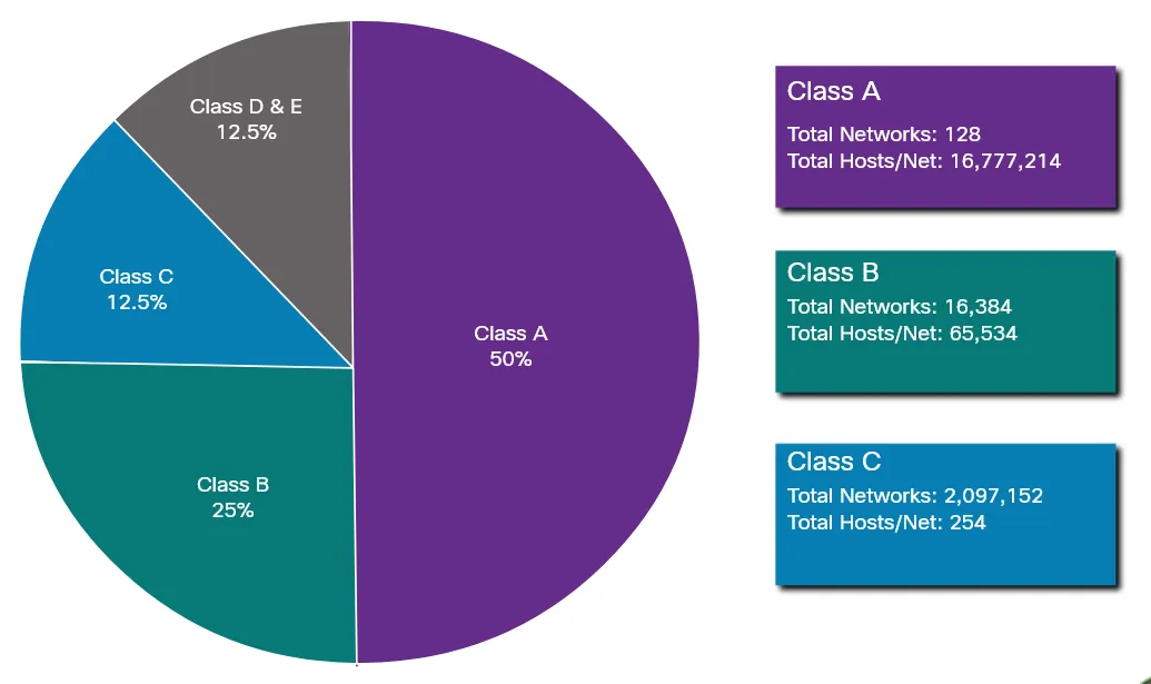
Classful Addressing
Section titled “Classful Addressing”Class A
Section titled “Class A”0.0.0.0/8 to 127.0..0.0/8 - Supporting networks with more then 16 million hosts.
Class B
Section titled “Class B”128.0.0.0/16 - 191.255.0.0/16 - Support networks with up to ~65K Hosts
Class C
Section titled “Class C”192.0.0.0/24 - 223.255.255.0/24 - Small networks with maximum 254 hosts
Class D and E
Section titled “Class D and E”Note: There is also a Class D multicast block consisting of 224.0.0.0 to 239.0.0.0 and a Class E experimental address block consisting of 240.0.0.0 - 255.0.0.0.
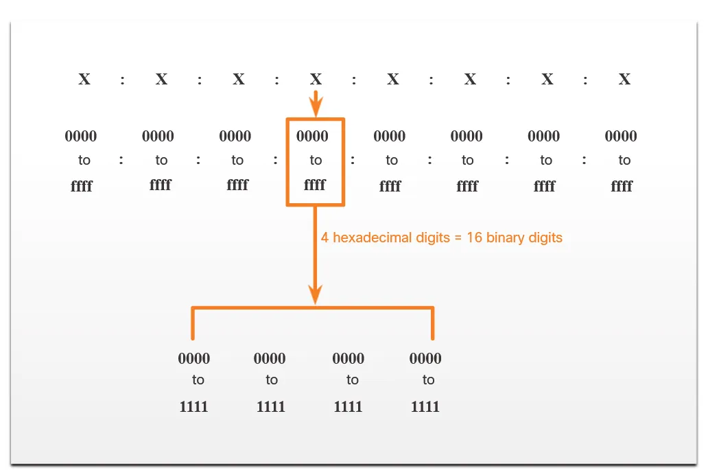
Internet Protocol Version 6 (IPv6) - Layer 3 (Network)
Section titled “Internet Protocol Version 6 (IPv6) - Layer 3 (Network)” IPV6 Addresses are represented using hex (0-9 A-F) in hextets. Addresses are 128 bits in length and written as a string of hexadecimal values. Every four bits is represented by a single hex digit. for a total of 32 hex values. The below is a representation of a preferred format which uses all 32 hex digits. This is not ideal in most circumstances due to lenghth with an example IPV6 address taking up a considerable length.
Example IP in preferred format: 2001:0db8:0000:1111:0000:0000:0000:0200
IPV6 Formatting Rules
Section titled “IPV6 Formatting Rules”Two rules to reduce hex digits representing an IPV6 address.
Rule 1
Section titled “Rule 1”Omit any leading zero’s as an example
2001:0db8:0000:1111:0000:0000:0000:0200
Becomes
2001:db8:0:1111:0:0:0:200
Rule 2
Section titled “Rule 2”Any single string of one or more 16 segments consisting of all zeroes can be represented by double colons (::) - Note: Double colon can only be used one and should be used on the longest contiguous zero hextets
2001:0db8:0000:1111:0000:0000:0000:0200
Becomes
2001:db8:0:1111::200
Base Header Format (40 Bytes)
Section titled “Base Header Format (40 Bytes)”| Byte 1 | Byte 2 | Byte 3 | Byte 4 | |
|---|---|---|---|---|
| Ver Traffic Class | Traffic Class Flow Label | Flow Label | Flow Label | Row 1 (4 bytes/32 bits) Ver (4 bits) - set to IPv6 Traffic Class (8 bits used for Quality of Service and Congestion control. Flow Label (20 bits) used by source to label sequence of packets - special handling requirements by ipv6 routers labelled. |
| Payload Length | Payload Length | Next Header | Hop Limit | Row 2 (4 bytes/32 bits) ∙Payload Length (16 bits): The length of the IPv6 payload (the data following the base header and any extension headers), in bytes.∙ Next Header (8 bits): Identifies the type of header immediately following the IPv6 header (e.g., a Transport layer header like TCP or UDP, or an IPv6 extension header).∙ Hop Limit (8 bits): Decremented by one by each node that forwards the packet. If the Hop Limit is reduced to zero, the packet is discarded. Similar to the IPv4 Time-to-Live (TTL). |
| Source IP | Source IP | Source IP | Source IP | Rows 3-6 (16 bytes / 128 bits)** Source IP Address (128 bits): The IPv6 address of the packet’s originator. This is 4 rows in total, as an IPv6 address is 128 bits long (16×8 bits). |
| Destination IP | Destination IP | Destination IP | Destination IP | Rows 7-10 (16 bytes / 128 bits): Destination IP Address (128 bits): The IPv6 address of the packet’s intended recipient. This is also 4 rows in total. |
Simple Network Management Protocol (SNMP)
Section titled “Simple Network Management Protocol (SNMP)”SNMP sits on the application layer and provides a standard specification for the network administrator to monitor, manage and configure network devices.
The Key features and functions include:
- Data Collection
- Fault Detection
- Remote Configuration
- Security (v3 )
The core components of an SNMP layer include:
SNMP Manager
Section titled “SNMP Manager”Central Software system that requests and processes data.
SNMP Agent
Section titled “SNMP Agent”Software on managed devices (Routers and Servers) which collects and forwards data to the manager.
Management Information base
Section titled “Management Information base”A tree-structured database of variables (OIDs) that defines what data can be queried on a device.
Versions
Section titled “Versions”- SNMP v1 - Least Secure
- SNMP v2c - most commonly used, improved performance but lacking strong security
- SNMP v3 - Current standard providing cryptographic security
Process
Section titled “Process”Manager to agent comms are done in the form of messages these messages are generally stored in the MIB (standardized database) - the MIB contains parameters/objects (OIDs)
SNMP v1 Messages
Section titled “SNMP v1 Messages”- GET - Retrieves information on agents
- GET-NEXT
- GET-RESPONSE
- SNMP SET - Modify or assign values to agents
- SNMP TRAP - Unsolicited alert sent from agent to manager when a predefined event occurs (e.g., interface down, threshold exceeded).